[STM32]: Making a custom i2c slave device using STM32F103
I2C is a serial protocol and its greatest advantage over other protocol is that it requires constant two wires irrespective of number of devices connected.
In this article, we shall discuss on how to design your own custom i2c slave device on stm32f103.
Why STM32F103?
- 32 bit, fast mcu speed 72 MHz.
- Cheap price <
2$and easily available. - I2C speed 100Khz and 400Khz supported.
- Interrupt & DMA support on i2c.
- appoint cpu intensive work to i2c slave e.g. motor control, adc sampling etcs.
Requirements
- stm32f103 blue pill board or similar
- i2c master (Arduino)
Custom i2c slave device
We are going to design a simple math calculator which requires two numbers (1 byte size) as input and it provides addition, subtraction and multiply of those two numbers as a reply to master query.
In slave mode, its not recommended to use polling method since ADDR event might be missed by slave in case of slave is doing some other tasks.
This would make i2c master to get stuck waiting for ADDR flag to be set. These are the reasons why its recommended to use ADDR and STOPF
using events and manage data transfers using interrupts or DMA.
We would use i2c event interrupt to handle this.
Design
Slave registers
We need to design our device registers or commands which is queried by master to control our custom slave device.
- SET_NUMBERS_REG 0x01
master writes three bytes after writing slave address on i2c line.
[START][Addr << 1 + 0] [SET_NUMBERS_REG][n1][n2][STOP] - GET_ADD_REG 0x02
master sets the register first and then read two bytes.
[START][Addr << 1 + 0][GET_ADD_REG][STOP]
[START][Addr << 1 + 1][ReadByte1][ReadByte2][STOP] - GET_SUB_REG 0x03
master sets the register first and then read two bytes.
[START][Addr << 1 + 0][GET_SUB_REG][STOP]
[START][Addr << 1 + 1][ReadByte1][ReadByte2][STOP] - GET_MUL_REG 0x04
master sets the register first and then read two bytes.
[START][Addr << 1 + 0][GET_MUL_REG][STOP]
[START][Addr << 1 + 1][ReadByte1][ReadByte2][STOP]
Code
I shall be using libopencm3 library but this code can be easily ported to other libraries.
SDA and SCL of I2C1 are PB7 and PB6 respectively.
i2c1_ev_isr is the interrupt function for i2c events. To enable this ISR function, we need to call i2c_enable_interrupt()
and enable both interrupt events namely I2C_CR2_ITEVTEN and I2C_CR2_ITBUFEN along with nvic interrupt NVIC_I2C1_EV_IRQ.
Lets write our i2c setup function.
static void
i2c_slave_init(uint8_t ownaddress)
{
   rcc_periph_clock_enable(RCC_GPIOB);
   rcc_periph_clock_enable(RCC_I2C1);

   nvic_enable_irq(NVIC_I2C1_EV_IRQ);

   // configure i2c pins
   gpio_set_mode(GPIOB, GPIO_MODE_OUTPUT_50_MHZ,
                 GPIO_CNF_OUTPUT_ALTFN_OPENDRAIN, GPIO_I2C1_SDA); //PB7
   gpio_set_mode(GPIOB, GPIO_MODE_OUTPUT_50_MHZ,
                 GPIO_CNF_OUTPUT_ALTFN_OPENDRAIN, GPIO_I2C1_SCL); //PB6

   i2c_peripheral_disable(I2C1);

   i2c_set_speed(I2C1, i2c_speed_sm_100k, I2C_CR2_FREQ_36MHZ);
   i2c_set_own_7bit_slave_address(I2C1, ownaddress);
   i2c_enable_interrupt(I2C1, I2C_CR2_ITEVTEN | I2C_CR2_ITBUFEN);
   i2c_peripheral_enable(I2C1);

   // slave needs to acknowledge on receiving bytes
   // set it after enabling Peripheral i.e. PE = 1
   i2c_enable_ack(I2C1);
}
Lets write our logic for handling data into ISR function.
//i2c1 event ISR
extern "C" void i2c1_ev_isr(void)
{
   uint32_t sr1, sr2;

   sr1 = I2C_SR1(I2C1);

   // Address matched (Slave)
   if (sr1 & I2C_SR1_ADDR)
     {
        reading = 0;
        read_p = buf;
        write_p = ((volatile uint8_t *)(&val) + 1);
        writing = 2;
        //Clear the ADDR sequence by reading SR2.
        sr2 = I2C_SR2(I2C1);
        (void) sr2;
     }
   // Receive buffer not empty
   else if (sr1 & I2C_SR1_RxNE)
     {
        //ignore more than 3 bytes reading
        if (reading > 3)
          return;
        //read bytes from slave
        *read_p++ = i2c_get_data(I2C1);
        reading++;
     }
   // Transmit buffer empty & Data byte transfer not finished
   else if ((sr1 & I2C_SR1_TxE) && !(sr1 & I2C_SR1_BTF))
     {
        //send data to master in MSB order
        i2c_send_data(I2C1, *write_p--);
        writing--;
     }
   // done by master by sending STOP
   //this event happens when slave is in Recv mode at the end of communication
   else if (sr1 & I2C_SR1_STOPF)
     {
        i2c_peripheral_enable(I2C1);

        if (buf[0] == MYSLAVE_GET_ADD_RESULT)
          val = buf[1] + buf[2];
        else if (buf[0] == MYSLAVE_GET_SUB_RESULT)
          val = buf[1] - buf[2];
        else if (buf[0] == MYSLAVE_GET_MUL_RESULT)
          val = buf[1] * buf[2];
     }
 //this event happens when slave is in transmit mode at the end of communication
   else if (sr1 & I2C_SR1_AF)
     {
        //(void) I2C_SR1(I2C1);
        I2C_SR1(I2C1) &= ~(I2C_SR1_AF);
     }
}
our main function is given below.
int main( void )
{
   //set STM32 to 72 MHz
   rcc_clock_setup_pll(&rcc_hse_configs[RCC_CLOCK_HSE8_72MHZ]);
   // Enable GPIOC clock
   rcc_periph_clock_enable(RCC_GPIOC);
   //Set GPIO13 (inbuild led connected) to 'output push-pull'
   gpio_set_mode(GPIOC, GPIO_MODE_OUTPUT_2_MHZ, GPIO_CNF_OUTPUT_PUSHPULL,
                 GPIO13);
   //switch led off
   gpio_set(GPIOC, GPIO13);

   //initialize i2c slave
   i2c_slave_init(MYSLAVE_ADDRESS);

   while( 1 )
     {
        gpio_toggle(GPIOC, GPIO13);
        my_delay_1();
     }
}
I have put the code at github. Refer README.md for how to compile code and upload to stm32f103.
In Action
The below codes are typically the way i2c master would query to this custom i2c slave device.
This can be easily implemented on Arduino using Wire library.
static void
write_slave(uint8_t reg, uint16_t val)
{
i2c.busyWait();
i2c.start(MYSLAVE_ADDRESS, 0); //WRITE
i2c.write(reg);
i2c.write((val >> 8) & 0xFF);
i2c.write(val & 0xFF);
i2c.stop();
}
static uint16_t
read_slave(uint8_t reg)
{
//wait for busy
i2c.busyWait();
uint16_t value = 0;
i2c.start(MYSLAVE_ADDRESS, 0); //master wants to write
i2c.write(reg);
i2c.stop();
time::delay(100);
i2c.start(MYSLAVE_ADDRESS, 1); //master wants to read
//enable ACK for data recieve except the last bit
value = ((i2c.read() << 8) | i2c.read(true));
i2c.stop();
return value;
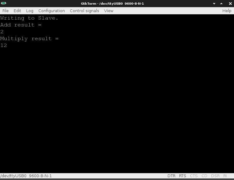
}Addition
//slave recieves 0x3, 01(N2), 01(N1) (data MSB LSB order)
write_slave(MYSLAVE_SET_REG, 0x0101);
time::delay(100);

uint16_t val = read_slave(MYSLAVE_GET_ADD_RESULT);
Multiplication
// Send 4 and 3
write_slave(MYSLAVE_SET_REG, 0x0403);
time::delay(100);

val = read_slave(MYSLAVE_GET_MUL_RESULT);