Use external clock as heartbeat to AVR and overclocking
Hello Everyone,
Recently I have ordered few samples from Linear Technologies which includes
I thank LT India to provide these awesome oscillators to me. I received samples from LT India, Banglore. I needed these to overclock AVR microcontrollers.
Soldering
These chips are in TSOT23-5 pkg and I wanted them to try on breadboard first. These ICs are really tiny.
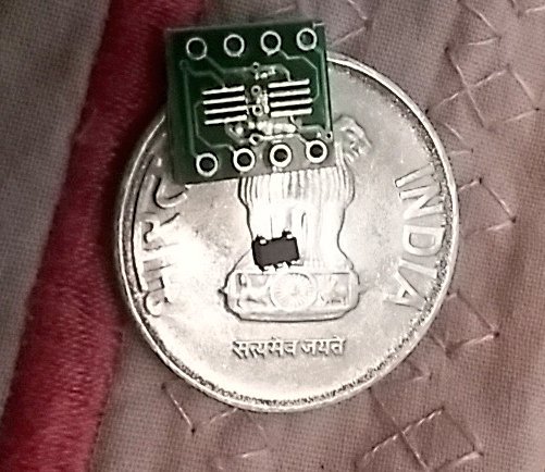
Luckily I had few TSOT23-8 to DIP adapters, so I soldered them nicely on these adapter boards. If you are new to smd soldering, I prefer you to check youtube videos on this topic.
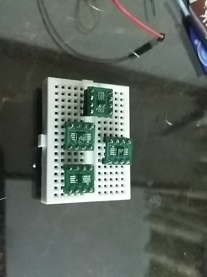
Advantages of using LTC1799
- It only uses
XTAL1pin of avr. 1KHz to 33 MHzFrequency Range.- Facilitates experimentation on testing lowest power consumption design on low speed. (say 10Khz or lesser)
Setup
Fuse settings
You have to change fuse settings of avr (attiny85 in our case). I used avr fuse calculator to find the correct settings for attiny85.
$ avrdude -c usbasp -p t85 -U lfuse:w:0xe0:m -U hfuse:w:0xdc:m -U efuse:w:0xff:mConnections
The port 5 of LTC1799 must be connected to attiny85 XTAL1 pin. I used R_set to 3.25kΩ so that I get 30 MHz clock from oscillator. My main aim was to test attiny85 running at 30 MHz. AVR attiny85 Datasheet recommends to run it up to 20 MHz only. Refer LTC1799 datasheet for the formula to program LTC1799. Its fairly easy though.
f_osc = 10MHz*((10k)/(N*R))
                          where N = 1 and R = 3.25K

f_osc = 10 * 1000000 * 10 * 1000 / (1 * 3.25 * 1000)
      = 30769230.769230768 Hz
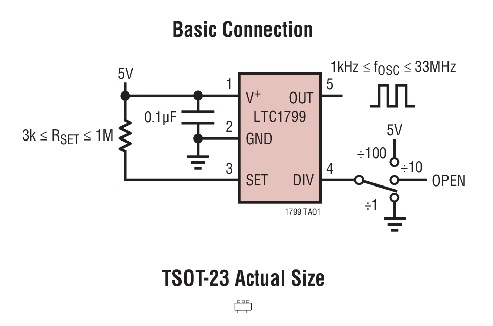 Reference: LTC1799 schematic
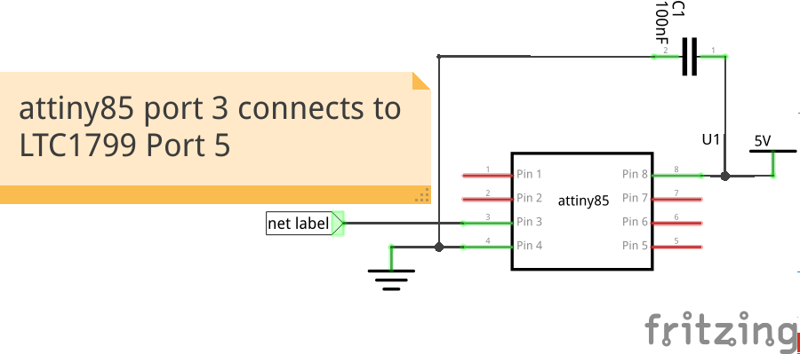 Running class blink program at 30 MHz.
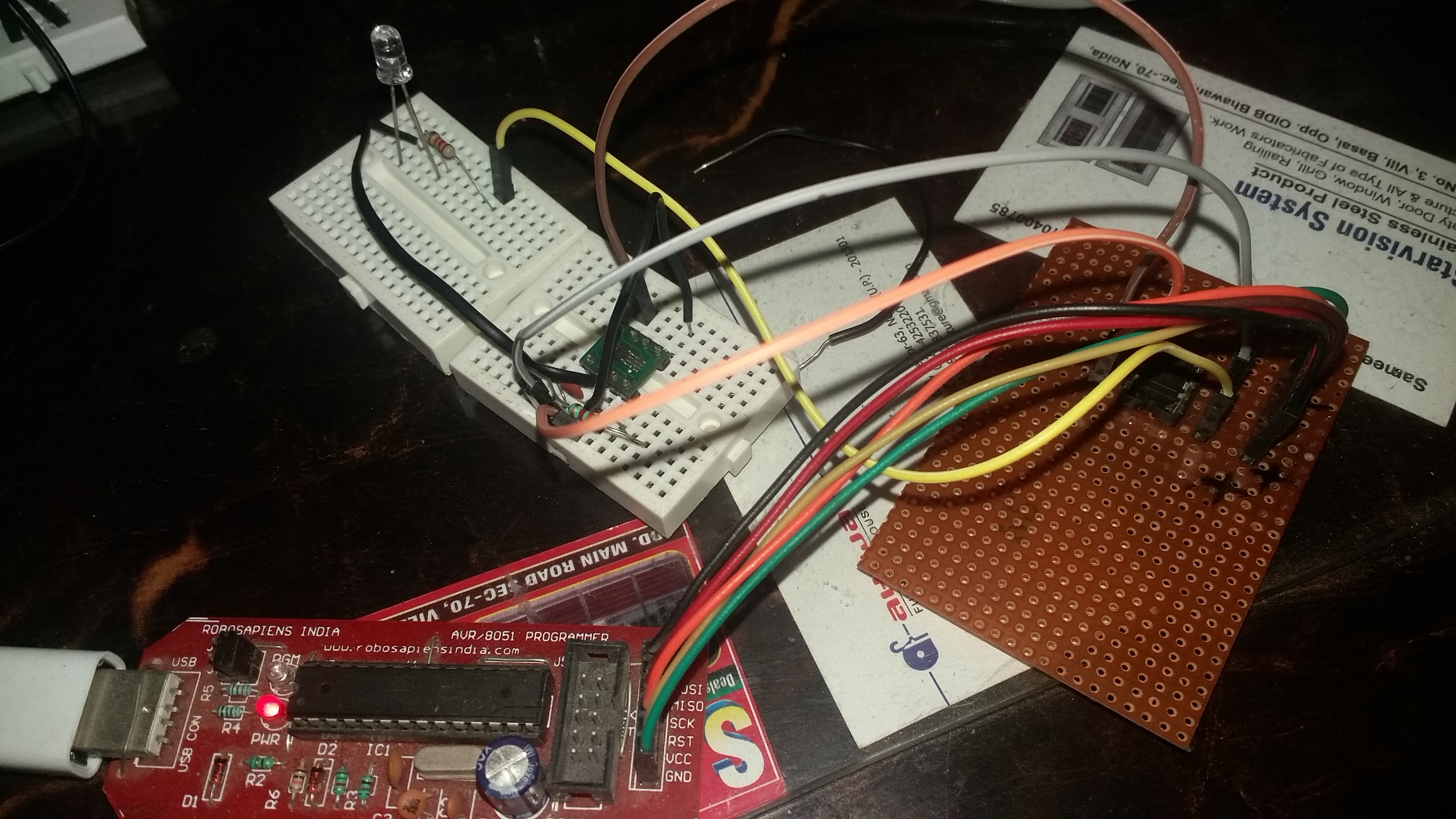
Verrifying with avrdude
$ avrdude -c usbasp -p t85

avrdude: warning: cannot set sck period. please check for usbasp firmware update.
avrdude: AVR device initialized and ready to accept instructions

Reading | ################################################## | 100% 0.02s

avrdude: Device signature = 0x1e930b (probably t85)

avrdude: safemode: Fuses OK (E:FF, H:DF, L:E0)

avrdude done.  Thank you.