[STM32]: FASTUSBasp programmer for AVR
Introduction
STM32F103C8T6 is a nice cheap board which have plenty of features especially USB2.0 full-speed and CAN support. I have loved Atmel AVR microcontrollers and used legendary USBasp programmer to program.
USBasp programmer is a great programmer and uses firmware-only USB driver. I wanted to create another AVR programmer which is similar to USBasp but with
real USB hardware to avoid connection issues which I had with USBasp before.
The price of this board is just 1.81$ in case you buy it from Aliexpress hence it was a good alternative to USBasp.
PCBs
Perf board

how to upload firmware
The pre-compiled binary is at firmware/fastusbasp.bin.
$ git clone https://github.com/amitesh-singh/FASTUSBasp
$ st-flash write firmware/fastusbasp.bin 0x08000000
how to compile from source and upload the firmware
If you want to build fastusbasp firmware from source code, follow below guidelines.
compile
Refer my post on how to setup stm32 devlopment environment on Arch linux. http://amitesh-singh.github.io/stm32/2017/04/09/setting-stm32-dev-environment-arch-linux.html
Make sure you have compiled libopencm3 library.
$ git clone https://github.com/amitesh-singh/FASTUSBasp
$ vi config.cmake  # set the libopencm3 path here
$ cmake .
$ make
Upload the firmware
using STLINK
connect st-link programmer to blue-pill and upload the firmware
$ make fastusbasp-upload
using serial port
Install stm32flash utility on linux.
To program stm32f103 via USART, you need to set BOOT0 as 1
and leave BOOT1 as 0.
Connect any usb to uart converter device and connect PA9 to RXD and PA10 to TXD and connect GND.
$ make fastusbasp-serialupload
How to program AVR MCUs
Probe AVR
$ sudo avrdude -c usbasp-clone -p m16

avrdude: AVR device initialized and ready to accept instructions

Reading | ################################################## | 100% 0.00s

avrdude: Device signature = 0x1e9403 (probably m16)

avrdude: safemode: Fuses OK (E:FF, H:D8, L:CF)

avrdude done.  Thank you.
Upload program to AVR
$ sudo avrdude -c usbasp-clone -p m16 -U flash:w:blink.hex

avrdude: AVR device initialized and ready to accept instructions

Reading | ################################################## | 100% 0.00s

avrdude: Device signature = 0x1e9403 (probably m16)
avrdude: NOTE: "flash" memory has been specified, an erase cycle will be performed
         To disable this feature, specify the -D option.
avrdude: erasing chip
avrdude: reading input file "blink.hex"
avrdude: input file blink.hex auto detected as Intel Hex
avrdude: writing flash (150 bytes):

Writing | ################################################## | 100% 0.02s

avrdude: 150 bytes of flash written
avrdude: verifying flash memory against blink.hex:
avrdude: load data flash data from input file blink.hex:
avrdude: input file blink.hex auto detected as Intel Hex
avrdude: input file blink.hex contains 150 bytes
avrdude: reading on-chip flash data:

Reading | ################################################## | 100% 0.01s

avrdude: verifying ...
avrdude: 150 bytes of flash verified

avrdude: safemode: Fuses OK (E:FF, H:D8, L:CF)

avrdude done.  Thank you.
Read flash
$ sudo avrdude -c usbasp-clone -p m16 -U flash:r:flash.bin:r

avrdude: AVR device initialized and ready to accept instructions

Reading | ################################################## | 100% 0.00s

avrdude: Device signature = 0x1e9403 (probably m16)
avrdude: reading flash memory:

Reading | ################################################## | 100% 0.33s

avrdude: writing output file "flash.bin"

avrdude: safemode: Fuses OK (E:FF, H:D8, L:CF)

avrdude done.  Thank you.

$ hexdump flash.bin
0000000 c029 0000 c02f 0000 c02d 0000 c02b 0000
0000010 c029 0000 c027 0000 c025 0000 c023 0000
0000020 c021 0000 c01f 0000 c01d 0000 c01b 0000
0000030 c019 0000 c017 0000 c015 0000 c013 0000
0000040 c011 0000 c00f 0000 c00d 0000 c00b 0000
0000050 c009 0000 2411 be1f e5cf e0d4 bfde bfcd
0000060 d002 c017 cfcd 9ab8 9ac0 ef2f ed83 e390
0000070 5021 4080 4090 f7e1 c000 0000 98c0 ef2f
0000080 ed83 e390 5021 4080 4090 f7e1 c000 0000
0000090 cfeb 94f8 cfff
Flash Read/Write speed
Flash Write speed: 15 KBps
Flash Read Speed: 52.5 KBps
Using with attiny13a
The default setting in attiny13a is to use 9.6 MHz internal oscillator. In this case, you need to decrease the CLK speed by providing -B option.
$ avrdude -c usbasp-clone -p t13 -B 1

avrdude: set SCK frequency to 750000 Hz
avrdude: AVR device initialized and ready to accept instructions

Reading | ################################################## | 100% 0.00s

avrdude: Device signature = 0x1e9007 (probably t13)

avrdude: safemode: Fuses OK (E:FF, H:FF, L:79)

avrdude done.  Thank you.
Bit clock speed
FASTUSBasp starts out with a fast ISP clock frequency (default: 3 MHz), so the -B bitclock option might be required to achieve stable communication in case F_CPU is bit low < 12MHz
Supported bitclock speed
default (without -B): 3 MHz
1.5 MHz
750 KHz
375 KHz
187.5 KHz
USB debug information
$ sudo lsusb -vv -d 16c0:

Bus 003 Device 005: ID 16c0:05dc Van Ooijen Technische Informatica shared ID for use with libusb
Device Descriptor:
  bLength                18
  bDescriptorType         1
  bcdUSB               2.00
  bDeviceClass          255 Vendor Specific Class
  bDeviceSubClass         0
  bDeviceProtocol         0
  bMaxPacketSize0        64
  idVendor           0x16c0 Van Ooijen Technische Informatica
  idProduct          0x05dc shared ID for use with libusb
  bcdDevice            2.00
  iManufacturer           1 ami
  iProduct                2 FASTUSBasp
  iSerial                 0
  bNumConfigurations      1
  Configuration Descriptor:
    bLength                 9
    bDescriptorType         2
    wTotalLength           18
    bNumInterfaces          1
    bConfigurationValue     1
    iConfiguration          0
    bmAttributes         0x80
      (Bus Powered)
    MaxPower              100mA
    Interface Descriptor:
      bLength                 9
      bDescriptorType         4
      bInterfaceNumber        0
      bAlternateSetting       0
      bNumEndpoints           0
      bInterfaceClass         0
      bInterfaceSubClass      0
      bInterfaceProtocol      0
      iInterface              0
can't get device qualifier: Resource temporarily unavailable
can't get debug descriptor: Resource temporarily unavailable
Device Status:     0x0000
  (Bus Powered)
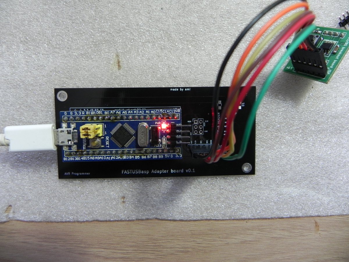
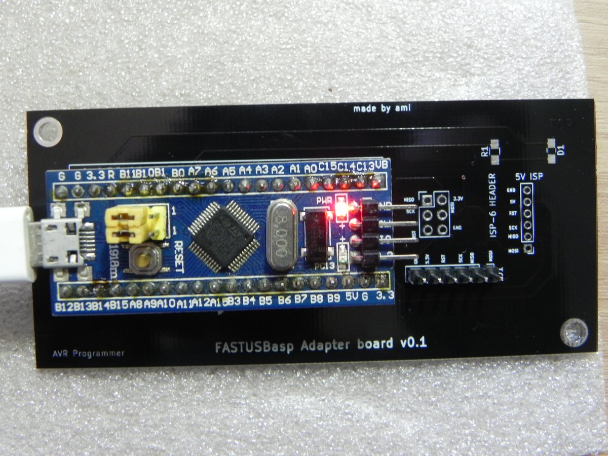
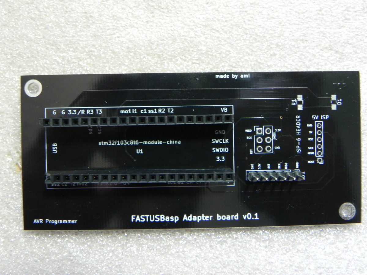
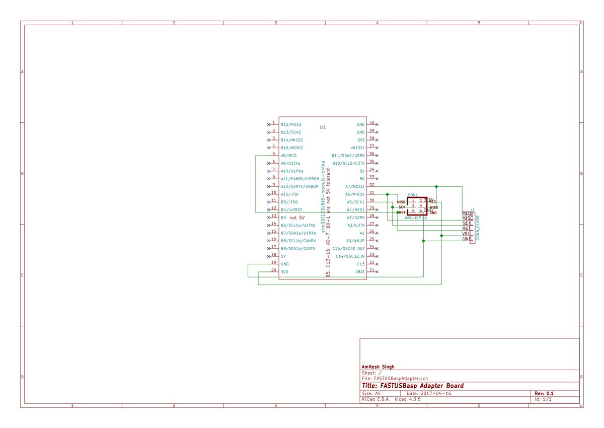
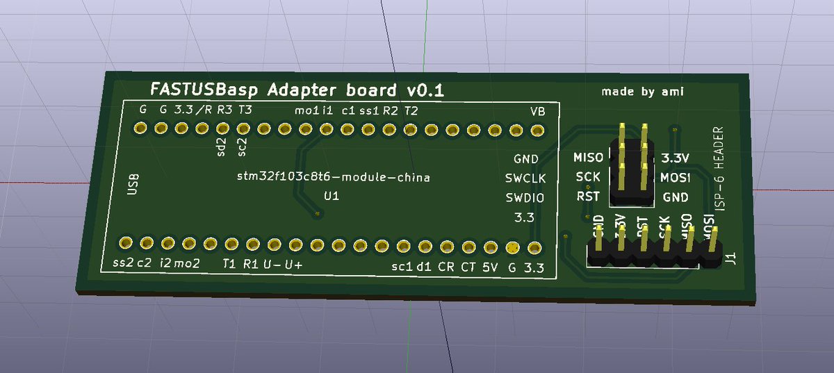
Adapter board
I have designed three types of PCBs for adapter board. The PCB version 3 can be found at
PCB v3.
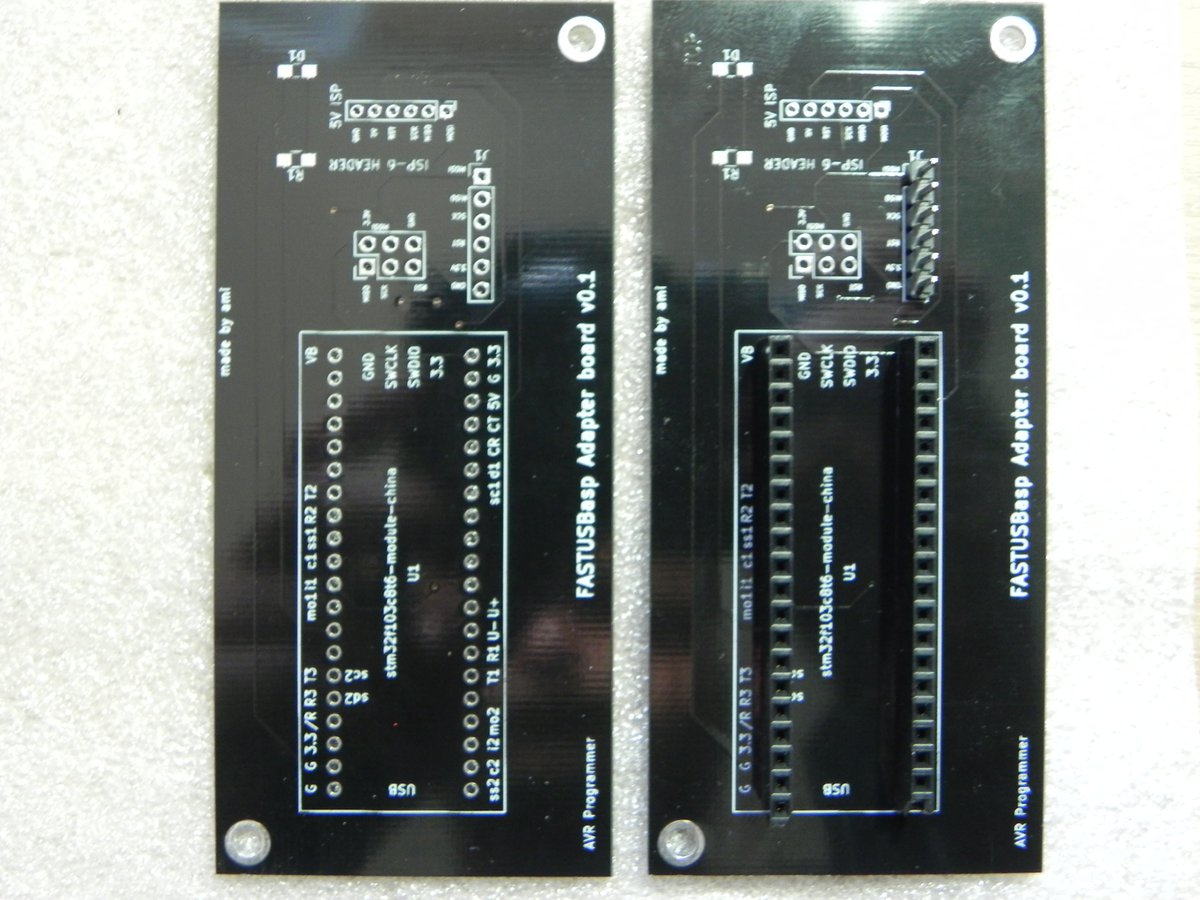
There is a panelized PCB which consists of 3 boards in
100x100 sq. mm area to save cost. You can download gerber files from
here.

I will be ordering panel PCBs soon. You can follow this project on Hackaday.
TODOs
firmware
- support more
SCKoptions. - support
TPI.
updates
15th Aug 2017
made the board on perfboard.