[STM32]: Blinking leds on stm32f407zgt6
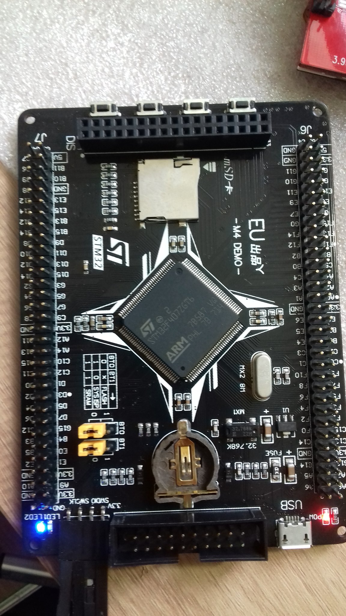
After working on STM32F103C8T6 aka “Blue-Pill” for a while, I have decided to have more adeventures by trying STM32f407ZGT6 board. This board costs around 14$ from Aliexpress and I got delived this board in 7 days from China.

Key Features
- Core: ARM® 32-bit Cortex® -M4 CPU with FPU, Adaptive real-time accelerator (ART Accelerator™) allowing 0-wait state execution from Flash memory, frequency up to 168 MHz, memory protection unit, 210 DMIPS/1.25 DMIPS/MHz (Dhrystone 2.1), and DSP instructions
- Memories
Up to 1 Mbyte of Flash memory
Up to 192+4 Kbytes of SRAM including 64-Kbyte of CCM (core coupled memory) data RAM Flexible static memory controller supporting Compact Flash, SRAM, PSRAM, NOR and NAND memories - LCD parallel interface, 8080/6800 modes
- Clock, reset and supply management 1.8 V to 3.6 V application supply and I/Os POR, PDR, PVD and BOR 4-to-26 MHz crystal oscillator Internal 16 MHz factory-trimmed RC (1% accuracy) 32 kHz oscillator for RTC with calibration Internal 32 kHz RC with calibration Sleep, Stop and Standby modes VBAT supply for RTC, 20×32 bit backup registers + optional 4 KB backup SRAM
- 3×12-bit, 2.4 MSPS A/D converters: up to 24 channels and 7.2 MSPS in triple interleaved mode
- 2×12-bit D/A converters
- General-purpose DMA: 16-stream DMA controller with FIFOs and burst support Up to 17 timers: up to twelve 16-bit and two 32-bit timers up to 168 MHz, each with up to 4 IC/OC/PWM or pulse counter and quadrature (incremental) encoder input
- Debug mode Serial wire debug (SWD) & JTAG interfaces Cortex-M4 Embedded Trace Macrocell™
- Up to 140 I/O ports with interrupt capability Up to 136 fast I/Os up to 84 MHz Up to 138 5 V-tolerant I/Os
- Up to 15 communication interfaces Up to 3 × I2 C interfaces (SMBus/PMBus) Up to 4 USARTs/2 UARTs (10.5 Mbit/s, ISO 7816 interface, LIN, IrDA, modem control) Up to 3 SPIs (42 Mbits/s), 2 with muxed full-duplex I2S to achieve audio class accuracy via internal audio PLL or external clock 2 × CAN interfaces (2.0B Active) SDIO interface
- Advanced connectivity USB 2.0 full-speed device/host/OTG controller with on-chip PHY USB 2.0 high-speed/full-speed device/host/OTG controller with dedicated DMA, on-chip full-speed PHY and ULPI 10/100 Ethernet MAC with dedicated DMA: supports IEEE 1588v2 hardware, MII/RMII
- 8- to 14-bit parallel camera interface up to 54 Mbytes/s
- True random number generator
- CRC calculation unit
- 96-bit unique ID
- RTC: subsecond accuracy, hardware calendar
For more information, go to STMicroelectronics product page
Install gcc and newlib
$ sudo pacman -S arm-none-eabi-gcc arm-none-eabi-newlibInstall stlink and openocd
stlink is a tool to download the compiled binary to the microcontroller and OpenOCD is an on-chip debugger. I shall cover OpenOCD in future tutorials.
$ sudo pacman -S stlink openocdinstall libopencm3
Libopencm3 is a nice opensource C library for cortex M0/M1/M3/M4 and other MCUs.
$ git clone https://github.com/libopencm3/libopencm3
$ cd libopencm3
$ make
This should compile without any issue.
Write your blink LED sketch
This boards has two LEDs at PC0 and PD3.
gpio_toggle() is the function to toggle the state of GPIOs and we would be using this function to blink the onboard leds.
#include <libopencm3/stm32/rcc.h>
#include <libopencm3/stm32/gpio.h>
#include <libopencm3/cm3/nvic.h>
#include <libopencm3/cm3/systick.h>

static volatile uint32_t system_ms = 0;

static void gpio_setup(void)
{
   // LED2 - PD3
   rcc_periph_clock_enable(RCC_GPIOD);
   gpio_mode_setup(GPIOD, GPIO_MODE_OUTPUT,
                   GPIO_PUPD_NONE, GPIO3);
   //LED1 - PC0
   rcc_periph_clock_enable(RCC_GPIOC);
   gpio_mode_setup(GPIOC, GPIO_MODE_OUTPUT,
                   GPIO_PUPD_NONE, GPIO0);
}

static void systick_setup(void)
{
   // 16MHz/8 = 2000000
   systick_set_clocksource(STK_CSR_CLKSOURCE_AHB_DIV8);

   // 2000000/2000 = 1000
   /* SysTick interrupt every N clock pulses: set reload to N-1 */
   systick_set_reload(1999);

   systick_interrupt_enable();

   /* Start counting. */
   systick_counter_enable();
}

void sys_tick_handler(void)
{
   system_ms++;
}

static void delay(uint32_t delay_ms)
{
   uint32_t future_ms = system_ms + delay_ms;
   while (future_ms > system_ms);
}

int main(void)
{
   //default speed is 16MHz set by libopencm3
   gpio_setup();
   systick_setup();

   while (1)
     {
        gpio_set(GPIOC, GPIO0);
        delay(400);
        gpio_clear(GPIOC, GPIO0);
        gpio_set(GPIOD, GPIO3);
        delay(400);
        gpio_clear(GPIOD, GPIO3);
     }

   return 0;
}
svn command can be used to download complete blink sample code.
$ svn export https://github.com/amitesh-singh/amiduino/trunk/stm32/f4/systick
A    systick
A    systick/Makefile
A    systick/libopencm3-examples-rules.mk
A    systick/libopencm3-examples-stm32f4.mk
A    systick/skeleton.c
A    systick/skeleton.ld
Exported revision 367.

$ cd systick/
$ ls
libopencm3-examples-rules.mk  libopencm3-examples-stm32f4.mk
Makefile  skeleton.c  skeleton.ld
You might need to modify the libopencm3 repo path in libopencm3-examples-rules.mk. In my case, it is set to $(HOME)/repos/libopencm3.
libopencm3-examples-rules.mk
 ...

 ###############################################################################
 # Source files

 OBJS     += $(BINARY).o


 ifeq ($(strip $(OPENCM3_DIR)),)
 # user has not specified the library path, so we try to detect it

 # where we search for the library
 #LIBPATHS := ./libopencm3 ../../../../libopencm3 ../../../../../libopencm3
 LIBPATHS := $(HOME)/repos/libopencm3
 ..
 ..
Build the blink program.
$ make
  CC      skeleton.c
  LD      skeleton.elf
  OBJCOPY skeleton.bin
Uploading the program
You will need ST Link V2 programmer to upload the code.
$ st-flash write skeleton.bin 0x08000000
st-flash 1.3.0
2017-09-02T12:45:20 INFO src/usb.c: -- exit_dfu_mode
2017-09-02T12:45:21 INFO src/common.c: Loading device parameters....
2017-09-02T12:45:21 INFO src/common.c: Device connected is: F4 device, id 0x10076413
2017-09-02T12:45:21 INFO src/common.c: SRAM size: 0x30000 bytes (192 KiB), Flash: 0x100000 bytes (1024 KiB) in pages of 16384 bytes
2017-09-02T12:45:21 INFO src/common.c: Attempting to write 908 (0x38c) bytes to stm32 address: 134217728 (0x8000000)
Flash page at addr: 0x08000000 erased
2017-09-02T12:45:21 INFO src/common.c: Finished erasing 1 pages of 16384 (0x4000) bytes
2017-09-02T12:45:21 INFO src/common.c: Starting Flash write for F2/F4/L4
2017-09-02T12:45:21 INFO src/flash_loader.c: Successfully loaded flash loader in sram
enabling 32-bit flash writes
size: 908
2017-09-02T12:45:21 INFO src/common.c: Starting verification of write complete
2017-09-02T12:45:21 INFO src/common.c: Flash written and verified! jolly good!
You should see two blue LEDs blinking.
New stm32f407 board. It blinks. #libopencm3 #stm32 pic.twitter.com/zt13BxRfAQ
— FAITH + 1 (@amitesh_singh) September 2, 2017